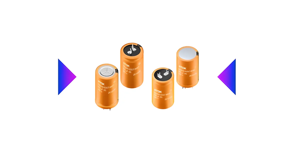
 Thermal constraints in on-board chargers usually reveal themselves long before the schematic looks finished. Ripple currents rise with switching frequency, case temperatures climb faster than simulations imply, and the DC link capacitor becomes the part that determines where heat can actually go. In 800V battery systems, the stress on that capacitor grows quickly. TDK’s B43655 and B43656 snap-in series fit that environment by being designed around how forced cooling and ripple density actually behave, not how they look in idealized conditions.
DC Link Behavior Under Forced Cooling in 800V Platforms
When an OBC is built around an 800V architecture, the DC link capacitor stops being a passive reservoir and becomes a thermal component. The B43655 series sits at 475V and 500V ratings with capacitances that reach toward the higher hundreds of microfarads. That combination makes it usable across the split rails found in many next-generation charger stages. ESR values can fall near the hundred milliohm range at room temperature, which helps keep switching losses contained when ripple current is high at elevated temperatures.
Ripple figures at +105°C approach the multi-amp region. At those levels, heat extraction becomes the bottleneck rather than voltage rating, which is why this series is built for base cooling. The useful life exceeding three thousand hours at +105°C reflects what happens when capacitors spend their lifetime close to a power semiconductor module rather than in open airflow.
Handling High Ripple Density in Compact Topologies
The B43656 series pushes ripple capacity further for high-power charger designs where current spikes occur during rapid load transitions. In those circuits, ripple values near four amps at elevated temperature are not unusual. Having a capacitor that can absorb that kind of stress without forcing layout compromises helps designers place components where thermal paths are shortest rather than where tolerance margins are widest.
Compact diameter options from roughly the low twenties to mid thirties millimeters allow these devices to sit in confined mechanical envelopes where airflow and forced cooling have specific paths. That range of dimensions matters in OBCs where inductors, power modules, and thermal plates already dominate the mechanical outline.
Placement, Snap-In Mounting, and Real Layout Constraints
Snap-in capacitors sound simple until vibration and thermal cycling are factored in. These components use construction choices meant to survive the conditions common in electric vehicle chargers where temperature swings occur repeatedly. Some variants include tighter length tolerances, which affects automated placement and mechanical fit inside dense assemblies. ESR stability through thermal cycles also determines how predictable the capacitor behaves when current surges occur during charger startup or during phase changes in the power factor correction stage.
These capacitors are built around AEC-Q200 requirements. That qualification matters because automotive OBCs must maintain reliability even when mounted close to heat sources. Forced cooling helps, but only when the capacitor’s internal construction handles both ripple stress and thermal gradients.
DC Link Choices in Future OBC Designs
Next-generation chargers move toward higher voltages, faster switching, and tighter mechanical envelopes. Ripple currents rise with efficiency targets. Capacitor choices become part of the thermal equation instead of a simple electrical requirement. The B43655 and B43656 series align with that direction by offering compact sizes, controlled ESR, and ripple handling that reduces how often layout engineers must compromise between space and heat paths.
Learn more and read the original announcement at www.tdk.com
You may also like